Technical Activities
Industrial 3D Modeling Methods: an introduction
By Jacopo V, consultant at AYES Italy
3D modeling is the process of developing a mathematical representation of any surface of an object in three dimensions via specialized software.
In any mechanical design project, there are two different 3D modeling methods which can be used: “Top-Down” and “Bottom-Up”.
The choice of the method depends on:
- The characteristics of the product to be designed;
- External constraints such as dimensions, complexity of the assembly, process technology;
- Design Software used.
Although it is possible that the project final design be identical regardless of the method selected, “Top-Down” procedure offers a higher level of flexibility (in terms of change management process), resulting in decreasing risk of design conflicts and errors.
Flexibility is the key to solid and easy-to-use product design, as it allows preserving the integrity of the final design purpose throughout the process.
The “Bottom-up” Method
“Bottom-Up” remains nowadays the best known and most commonly used modeling approach.
This is because it is the simplest, the most immediate and intuitive technique. This method is effective mainly in two cases:
· To assemble already designed parts of an object.
· To build small and rather simple assemblies.
The “Bottom-Up” method consists first in designing individually each component of the assembly.
Then the parts are connected to form larger components, which are interconnected to create a complete system.
One advantage of this design process is that it allows to clearly identify the variables that have an influence on the individual components, and thus, on the entire system.
The “Top-Down” Method
“Top-Down” 3D modeling approach relies on the principle that it is possible to deduce the design of the individual components of a mechanical ensemble from analyzing the final assembly characteristics.
These components are linked together through dimensional relationships and external constraints. This approach leads to establishing a logical and sequential chain gathering all the information involved in the study.
3D modeling “Top-Down” method can be implemented using parametric 3D CAD software. Such software platforms allow to create rigid links between components and to maintain the uniqueness of the project data.
An example of this method is illustrated in Fig. 1 where an engine is first schematized as parallelepiped (on top) in order to establish the overall dimension and to verify compliance with external constraints. Subsequently it is divided in subgroups (below), each of which following the same procedure down to the final detailed design of all components.
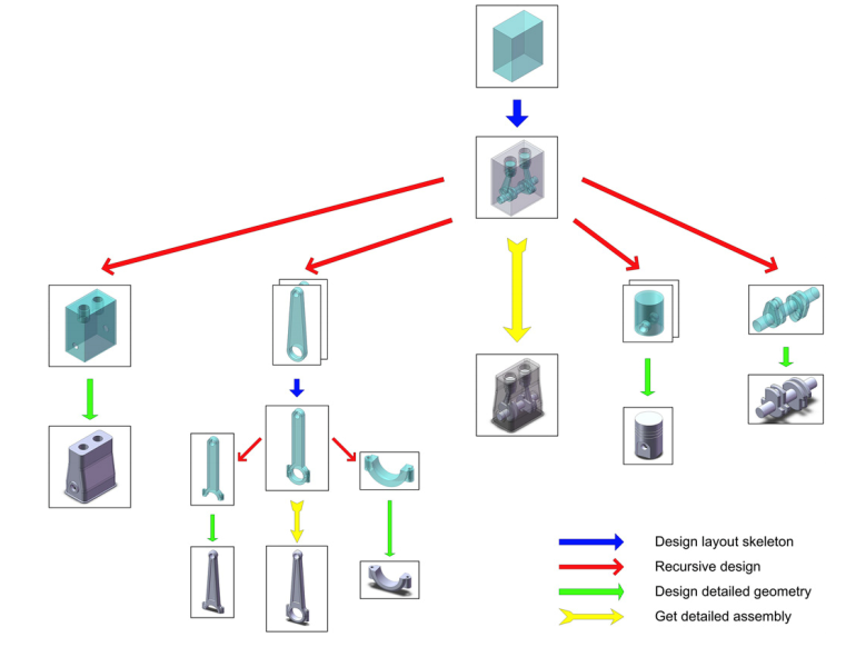
The whole mechanical design process using Top-Down method can be summed up in two fundamental points:
1. Project study
2. Components design
Project Study is a two-dimensional or three-dimensional representation without any mechanical design standardized formalism. In particular, the project functional objective and the components sizing are represented schematically: shape of the objects, datum references, dimensional relationships.
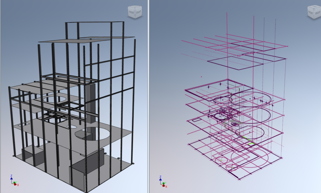
This phase is necessary to provide the designer with a clear and global vision of the project. In parametric 3D CAD software platforms, the study is generally represented through a “skeleton”, which can be both a 2D or a 3D representation (Fig. 2).
On the image below (right) you can see the 2D skeleton, drawn on plans located at different heights generating a global 3D skeleton of the project. The final 3D model is shown on the image below (left).
The final phase consists in designing the components. This can be performed with different modeling methods (solid modeling, surface modeling, etc..).
AYES can adapt to any specific project design method or tool. We also have the capacity to help our customers in selecting one method or one tool over others, after an in-depth analysis of their project environment characteristics.